Tag: railroad switch
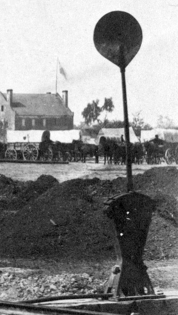 Wikipedia says: A railroad switch (AE), turnout, or [set of] points (BE) is a mechanical installation enabling railway trains to be guided from one track to another, such as at a railway junction or where a spur or siding branches off.
A switch (points) consist of a pair of linked tapering rails, known as points (switch rails or point blades), lying between the diverging outer rails (the stock rails). These points can be moved laterally into one of two positions to direct a train coming from the point blades toward the straight path or the diverging path. A train moving from the narrow end toward the point blades (i.e. it will be directed to one of the two paths, depending on the position of the points) is said to be executing a facing-point movement.
Unless the switch is locked, a train coming from either of the converging directs will pass through the points onto the narrow end, regardless of the position of the points, as the vehicle’s wheels will force the points to move. Passage through a switch in this direction is known as a trailing-point movement.
A switch generally has a straight “through” track (such as the main-line) and a diverging route. The handedness of the installation is described by the side that the diverging track leaves. Right-hand switches have a diverging path to the right of the straight track, when coming from the point blades, and a left-handed switch has the diverging track leaving to the opposite side. In many cases, such as rail yards, many switches can be found in a short section of track, sometimes with switches going both to the right and left (although it is better to keep these separated as much as feasible). Sometimes a switch merely divides one track into two; at others, it serves as a connection between two or more parallel tracks, allowing a train to switch between them. In many cases, where a switch is supplied to leave a track, a second is supplied to allow the train to reenter the track some distance down the line; this allows the track to serve as a siding, allowing a train to get off the track to allow traffic to pass (this siding can either be a dedicated short length of track, or formed from a section of a second, continuous, parallel line), and also allows trains coming from either direction to switch between lines; otherwise, the only way for a train coming from the opposite direction to use a switch would be to stop, and reverse through the switch onto the other line, and then continue forwards (or stop, if it is being used as a siding).
A straight track is not always present; for example, both tracks may curve, one to the left and one to the right (such as for a wye switch), or both tracks may curve, with differing radii, while still in the same direction.
On early lines, vehicles were moved between tracks by means of sliding rails. The switch was patented by Charles Fox in 1832.
Prior to the widespread availability of electricity, switches at heavily travelled junctions were operated from a signal box constructed near the tracks through an elaborate system of rods and levers. The levers were also used to control railway signals to control the movement of trains over the points.
Operation
A railroad car’s wheels are guided along the tracks by coning of the wheels. Only in extreme cases does it rely on the flanges located on the insides of the wheels. When the wheels reach the switch, the wheels are guided along the route determined by which of the two points is connected to the track facing the switch. In the illustration, if the left point is connected, the left wheel will be guided along the rail of that point, and the train will diverge to the right. If the right point is connected, the right wheel’s flange will be guided along the rail of that point, and the train will continue along the straight track. Only one of the points may be connected to the facing track at any time; the two points are mechanically locked together to ensure that this is always the case.
A mechanism is provided to move the points from one position to the other (change the points). Historically, this would require a lever to be moved by a human operator, and some switches are still controlled this way. However, most are now operated by a remotely controlled electric motor or by pneumatic or hydraulic actuation, called a point machine. This both allows for remote control and for stiffer, strong switches that would be too difficult to move by hand, yet allow for higher speeds.
In a trailing-point movement (running through the switch in the wrong direction while they are set to turn off the track), the flanges on the wheels will force the points to the proper position. This is sometimes known as running through the switch. Some switches are designed to be forced to the proper position without damage. Examples include variable switches, spring switches, and weighted switches.
Showing 1–16 of 29 results
-
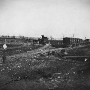
Image ID: AABH
$5.99 -
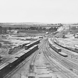
Image ID: AABT
$3.99 -
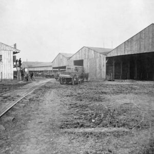
Image ID: AADW
$6.99 -
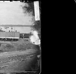
Image ID: AAHS
$4.99 -
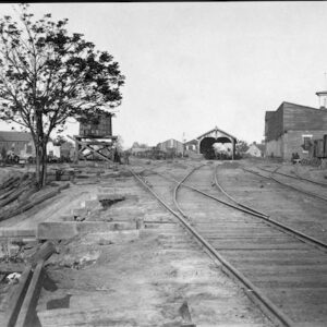
Image ID: AAJO
$5.99 -
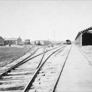
Image ID: AAKI
$1.99 -
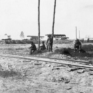
Image ID: AANE
$5.99 -
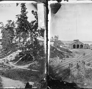
Image ID: ABBX
$2.99 – $4.99 This product has multiple variants. The options may be chosen on the product page -
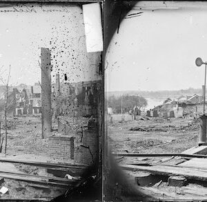
Image ID: ABDO
$3.99 – $4.99 This product has multiple variants. The options may be chosen on the product page -
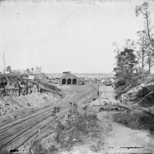
Image ID: ABEM
$4.99 -
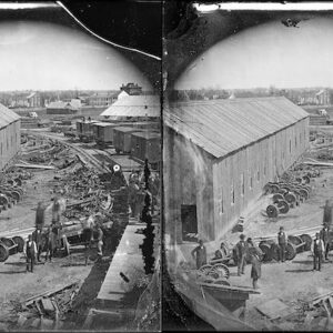
Image ID: AEOR
$3.99 -
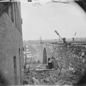
Image ID: AEZU
$4.99 – $6.99 This product has multiple variants. The options may be chosen on the product page -

Image ID: AIMT
$4.99 -
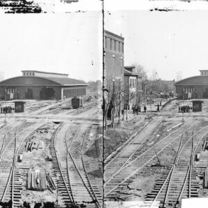
Image ID: AJDL
$6.99 -
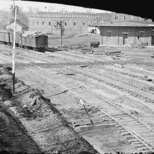
Image ID: AJDM
$5.99 -
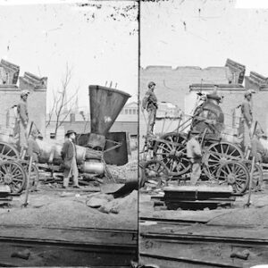
Image ID: AJED
$6.99